Monday, April 28, 2014

Monitor Actuator Pair Design Pattern

A previous post discussed patterns for safe systems, including using redundant processors that cross-check. Another accepted pattern for ensuring that there is no single point failure is a Monitor-Actuator Pair. In this architectural pattern, the "actuator" performs the control computation or other safety critical function. The "monitor" checks that the actuator is performing safely. If either the monitor or the actuator detects a problem, typically they do a mutual shut-down as with a replicated pair. The motivation to use a monitor-actuator pattern is that the monitor can often be simpler than the actuator, helping reduce system cost in both direct and indirect ways.

Consequences:  When using a monitor-actuator safety architecture, the monitor must be able to mitigate faults without requiring that the actuator software participates in that mitigation. The consequence of implementing a monitor-actuator pair improperly is that when the actuator experiences a fault, that fault may not be mitigated. 

Accepted Practice:
  • All monitor functions must execute on a separate microcontroller or other isolated hardware platform. This is to ensure that execution errors in the actuator cannot compromise the operation of the monitor.
  • When a fault is detected, the monitor must mitigate the fault (e.g., do a system reset or close the throttle) regardless of any function performed (or not performed) by the actuator. This is to ensure that execution errors in the actuator cannot prevent fault mitigation from succeeding. 
Discussion:

A well established design technique for mitigating software errors is to have two independent hardware components operate as a “monitor-actuator” CPU pair. The actuator CPU is the component that actually performs the computation or control function. For example, the actuator might compute a throttle angle command based on accelerator position. (The name “actuator” is just a role that is played – it can include calculation and other functions.) An independent monitor Chip is used to avoid having the actuator CPU be a single point of failure. The general assumption is that the actuator CPU may fail in some detectable way, and the monitor’s job is to detect and mitigate any such failure. A common mitigation technique is resetting the actuator CPU. (Note that for the remainder of this section I use the term “actuator” for this design pattern to mean an actuator CPU, and not a physical actuation output device.)


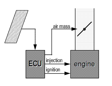
Monitor-Actuator Design Pattern. (Douglass 2002, Section 9.6)

The monitor must be implemented as an independent microcontroller that does an acceptance test (a computation to determine if the actuator’s outputs are safe) or other computation to ensure that the actuator is operating properly. The precise check on the actuator’s output used is application specific, and multiple such checks might be appropriate for a particular system. If the monitor detects that the actuator is not behaving in a safe manner, the monitor performs a fault mitigation function. 

An example of such a monitor-actuator pair would be a throttle control microcontroller (the actuator) and an associated independent monitor microcontroller. If the throttle actuator CPU hangs or issues an unsafe throttle command, the monitor detects that condition and performs a fault mitigation action such as resetting the throttle actuator CPU. To perform this function, the monitor observes data being used by the actuator to perform computations as well as observes the outputs of the actuator. The monitor then decides if the throttle position is reasonable given the observed inputs (including, for example, brake pedal position) and resets the actuator when the checks fail. Examples of checks that would be expected in this sort of system would be a heartbeat check designed along the lines of a watchdog timer approach (ensuring the actuator is processing data periodically rather than being dead for some reason), and checking to ensure that commanded throttle position is reasonable given inputs to the actuator, such as the brake pedal position.

Proper operation of a monitor-actuator pair requires that the monitor has an ability to perform fault mitigation regardless of any execution problem that may be taking place in the actuator. For example, the monitor might use a hardware control line to reset the actuator and move the physical actuator to a safe position. Any assumption that the actuator will cooperate in fault mitigation (e.g., via a software task on the actuator accepting a reset request and initiating a reset), is considered a bad practice. Moreover, there should be no way for the actuator to inhibit the mitigation even if a software defect on the actuator actively tries to do so via faulty operation. The reason for this is that if the actuator is acting in a way that is defective, then relying on that defective component to perform any function properly (including self fault mitigation such as setting a trouble code or resetting) is a bad practice. Rather, the monitor must have a complete and independent ability to mitigate a fault in the actuator, regardless of the state of the actuator.

Selected Sources:

Douglass 2002 describes this pattern under in section 9.6. Douglass summarizes the operation as: “In the Monitor-Actuator Pattern, an independent sensor maintains a watch on the actuation channel looking for an indication that the system should be commanded into its fail-safe state.” The description emphasizes the need for independence of the two components.

“For the higher integrity levels, consider using an independent monitor processor to initiate a safe state.” (MISRA Software Guidelines 3.4.1.6.h, page 36). MISRA further makes it clear that the two “channels” (the monitor and the actuator) must “provide truly independent detection and reaction to errors” to provide safety mitigation (MISRA Report 2, p. 8, emphasis added).

Delphi’s automotive electronic throttle control system is said to use a primary processor and a redundant checking processor in keeping with this design practice, including an arrangement in which the second “processor performs redundant ETC sensor and switch reads.” (McKay 2000, pg. 8).

Safety standards also make it clear that the mere presence of a single point fault is unacceptable. For example, FAA DO-178b, the aviation software safety standard, specifically talks about a monitor/actuator pattern, saying that risk of failure is mitigated only if this condition (among several) is satisfied: “Independence of Function and Monitor: The monitor and protective mechanism are not rendered inoperative by the same failure condition that causes the hazard.”  (DO 178-b Section 2.3.3.c).

References:
  • Douglass, B. P., Real-Time Design Patterns: robust scalable architecture for real-time systems, Pearson Education, first printing, September 2002, copyright by Pearson in 2003.
  • MISRA, Development Guidelines for Vehicle Based Software, November 1994 (PDF version 1.1, January 2001).
  • MISRA, Report 2: Integrity, February 1995
  • McKay, D., Nichols, G. & Schreurs, B., Delphi Electronic Throttle Control Systems for Model Year 2000; Driver Features, System Security, and EOM Benefits. SAE 2000-01-0556, 2000.
  • Do-178b, Software considerations in airborne systems and equipment certification, Royal Technical Commission on Aviation, Dec 1, 1992.

Monday, April 21, 2014

Layered Defenses for Safety Critical Systems

Even if designers mitigate all single point faults in a design, there is always the possibility of some unexpected fault or combination of correlated faults that causes a system to fail in an unexpected way. Such failures should ideally never happen, but in practice no design analysis is perfectly comprehensive, especially if there are unconsidered correlations that make seemingly independent faults happen together, so they do happen. To mitigate such problems, system designers use layers of mitigation, which is a practice sometimes referred to as “defense in depth.”

Consequences: 
If a layered defensive strategy is defective, a failure can bypass intended mitigation strategies and result in a mishap.

Accepted Practices:
  • The accepted practice for layered systems is to ensure that no single point of failure, nor plausible combination of failures, exists which permits a mishap to occur. For layered defense purposes, a single point of failure includes even a redundant component subsystem (e.g., a 2oo2 redundant self-checking CPU pair might fail due to software defect present on both modules, so a layered defense provides an alternate way to recover from such a failure) 
  • The existence of multiple layers of protection is only effective if the net result gives complete, non-single-point-of-failure, coverage of all relevant faults.
  • The goal of layered defenses should be maximizing the fraction of problems that are caught at each layer of defense to reduce the residual probability of a mishap.
Discussion:

A layered defense system typically rests on an application of the principle of fault containment, in which a fault or its effects are contained and isolated so as to have the least effect on the system possible. The starting point for this is using fault containment regions such as 2oo2 systems or similar design patterns. But, a prudent designer admits that software faults or correlated hardware faults might occur, and therefore provides additional layers or protection.


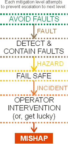
Layered defenses attempt to prevent escalation of fault effects.

The figure above shows the general idea of layered defenses from a fault tolerant computing perspective. First, it is ideal to avoid both design and run-time faults. But, faults do crop up, and so mechanisms and architectural patterns should be in place to detect and contain those faults using fault containment regions. If a fault is not contained as intended, then the system experiences a hazard in that its primary fault tolerance approach has not worked and the system has become potentially unsafe. In other words, some fraction of faults might not be contained, and will result in hazards.

Once a hazard has manifested, a "fail-safe" mitigation strategy can help reduce the chance of a bigger problem occurring. A fail safe might, for example, be an independent safety system triggered by an electro-mechanical monitor (for example, a pressure relief valve on a water heater that releases pressure if steam forms inside the tank). In general, the system is already in an unsafe operating condition when the fail-safe has been activated. But, successful activation of a fail-safe may prevent a worse event much of the time. In other words, the hope is that most hazards will be mitigated by a fail-safe, but a few hazards may not be mitigated, and will result in incidents.

If the fail-safe is not activated then an incident occurs. An incident is a situation in which the system remains unsafe long enough for an accident to happen, but due to some combination of operator intervention or just plain luck, a loss event is avoided. In many systems it is common to catch a lucky break when the system fails, especially if well trained operators are able to find creative ways to recover the system, such as by shifting a car's transmission to neutral or turning off the ignition when a car's engine over-speeds. (It is important to note that recovering such a system doesn't mean that the system was safe; it just means that the driver had time and training to recover the situation and/or got lucky.) On the other hand, if the operator doesn't manage to recover the system, or the failure happens in a situation that is unrecoverable even by the best operator, a mishap will occur resulting in property damage, personal injury, death, or other safety loss event. (The general description of these points is based on Leveson 1986, pp. 149-150.)

A well known principle of creating safety critical systems is that hazardous behavior displayed by individual components is likely to result in an eventual accident. In other words, with a layered defense approach, components that act in a hazardous way might lead to no actual mishap most times, because a higher level safety mechanism takes over, or just because the system gets “lucky.” However, the occurrence of such hazards can be expected to eventually result in an actual mishap, when some circumstance results in which the safety net mechanism fails. 

For example, a fault containment might work 99.9% of the time, and fail-safes might also work 99.9% of the time. Thousands of tests might show that one or another of these safety layers saves the day. But, eventually, assuming the probability the safety layers being effective is random and independent, both will fail for some infrequent situation, causing a mishap. (Two layers at 99.9% give unmitigated faults of: 0.1% * 0.1% = 0.0001%, which is unlikely to be seen in testing, but still isn't zero.)  The safety concept of avoiding single point failures only works if each failure is infrequent enough that double failures are unlikely to ever happen in the entire lifetime of the operational fleet, which can be millions or even billions of hours of exposure for some systems. Doing this in practice for large deployed fleets requires identifying and correcting all situations detected in which single point failures are not immediately and completely mitigated. You need multiple layers to catch infrequent problems, but you should always design the system so that the layers are never exercised in situations that occur in practice.

Selected Sources:

Most NASA space systems employ failure tolerance (as opposed to fault tolerance) to achieve an acceptable degree of safety. Failure tolerance means not only are faults tolerated within a particular component or subsystem, but the failure of an entire subsystem is tolerated. (NASA 2004 pg. 114) These are the famous NASA backup systems. “This is primarily achieved via hardware, but software is also important, because improper software design can defeat the hardware failure tolerance and vice versa.” (NASA 2004 pg. 114, emphasis added)

Some of the layered defenses might be considered to be forms of graceful degradation (e.g., as described by Nace 2001 and Shelton 2002). For example, a system might revert to simple mechanical controls if a 2oo2 computer controller does a safety shut-down. A key challenge for graceful degradation approaches is ensuring that safety is maintained for each possible degraded configuration.

See also previous blog posting on: Safety Requires No Single Points of Failure

References:
  • Leveson, N., Software safety: why, what, how, Computing Surveys, Vol. 18, No. 2, June 1986, pp. 125-163.
  • Nace, W. & Koopman, P., "A Graceful Degradation Framework for Distributed Embedded Systems," Workshop on Reliability in Embedded Systems (in conjunction with Symposium on Reliable Distributed Systems/SRDS-2001), October 2001.
  • NASA-GB-8719.13, NASA Software Safety Guidebook, NASA Technical Standard, March 31, 2004.
  • Shelton, C., & Koopman, P., "Using Architectural Properties to Model and Measure System-Wide Graceful Degradation," Workshop on Architecting Dependable Systems (affiliated with ICSE 2002), May 25 2002.
  • Monday, April 14, 2014

    Redundant Input Processing for Safety

    Redundant analog and digital inputs to a safety critical system must be fed to independent chips to ensure no single point failure exists.  (This posting is a follow-on to a previous post about single points of failure.)

    Consequences: If fully replicated input processing and validation is not implemented with complete avoidance of single points of failure, it is possible for a single fault to result in erroneous input values causing unsafe system operation.

    Accepted Practices:
    • A safety critical system must not have any single point of failure that results in a significant unsafe condition if that failure can reasonably be expected to occur during the operational life of the deployed fleet of systems. Redundant input processing is an accepted practice that can help avoid single point failures.
    Discussion:

    A specific instance of avoiding single points of failure involves the processing of data inputs. It is imperative that safety critical input signals be duplicated and processed independently to avoid a single point of failure in input processing.

    Analog inputs must be converted to digital signals via an A/D converter, which is a relatively complex apparatus that takes up a significant amount of chip area. For this reason, it is common to use a single shared A/D converter with multiple shared (“muxed”) inputs to that single converter. If redundant external inputs are run through the same A/D, this creates a single point of failure in the form of the A/D converter itself and the associated control circuitry.

    Mauser gives an example of this problem applied to automotive throttle control, showing that only a "true 2-channel system" (e.g., a 2oo2 system with redundant inputs) provides safety.


    Figures from Mauser 1999, pp. 731, 738-739 showing an example throttle control system that causes runaway unless a truly redundant system (dual CPUs plus dual A/D conversion) is used.

    Similarly, digital inputs that are processed in the same chip have common circuitry affecting their operation, which in typical chips includes a direction register that determines whether a digital pin is an input or output.

    For both analog and digital inputs, an additional way of looking at single point failures is that if both redundant input signals are processed on the same chip, that one chip is subject to arbitrary faults, with arbitrary fault behavior including the possibility of corrupting both inputs in a way that is both faulty and undetectable by other components in the system. Unless some independent means of ensuring system safety is present, such a single point of failure impairs system safety. An arbitrary fault on a single chip that processes both copies of an analog input sensor might declare the sensor to be fully activated, but within normal operational limits, resulting in that value being processed by the rest of the system whether the input is really active or not. For example, an embedded CPU in a car might think that the brake pedal is depressed, accelerator pedal is depressed, or parking brake is engaged despite the potential presence of redundant sensors on those controls if both sensors pass through the same A/D converter or digital input port and there is a common-mode hardware fault in those input processing circuits.

    Beyond the need to independently computer results on two different chips, there is an additional requirement for safety that each of the two chips independently and fully compare the inputs to detect any faults. For example, if chips A and B both process inputs, but only chip B compares them for correctness, then there is a single point of failure if chip B has a bad input and incorrectly reports the comparison as passing (this only counts as one failure because chip B can fail in an arbitrary way in which it both mis-interprets input B and "lies" about the comparison with input A being OK). A safe way to do such a comparison is that chip A compares both inputs, chip B compares both inputs, and the system only continues operation if both chip A and chip B agree that each of their comparisons validated the inputs as being consistent. Moreover, cross-checks on the outputs based on those inputs must also be performed to detect faults that occur after input processing. That generally leads to a 2oo2 architecture like the one shown below, with each FCR usually being a CPU chip.


    Sometimes both inputs go to both FCRs, but then it must be ensured that there is hardware isolation in place so that a hardware fault on one FCR can't propagate to the inputs of the other FCR via the shared input lines. Another complication is that redundant sensors often do not produce identical output values, and the problem of determining distributed agreement turns out to be very difficult even if all you need is an approximate agreement result. In general, once you have replication, getting agreement across the replicated copies of inputs and computations requires some effort (Poledna 1995). But, these are the sorts of issues that engineers routinely work through when creating safety-critical systems.

    In the end, having a single shared A/D converter or other input circuit for a safety critical system is inadequate. You must have two separate input processing circuits on two separate chips to have two independent Fault Containment Regions (e.g., using a 2oo2 architectural approach with redundant inputs). This is required to achieve safety for a high-integrity application, and any high-integrity embedded system that uses a shared A/D converter on a single chip to process redundant inputs is unsafe.

    References:
    • Mauser, Electronic throttle control – a dependability case study, J. Univ. Computer Science, 5(10), 1999, pp. 730-741.
    • Poledna, S., "Fault tolerance in safety critical automotive applications: cost of agreement as a limiting factor ", Fault-Tolerant Computing, 1995. FTCS-25. Digest of Papers., Twenty-Fifth International Symposium on , 27-30 Jun 1995 Page(s): 73 -8


    Monday, April 7, 2014

    Self-Monitoring and Single Points of Failure


    A previous post discussed single points of failure in general. Creating a safety-critical embedded system requires avoiding single points of failure in both hardware in software. This post is the first part of a discussion about examples of single points of failure in safety critical embedded systems.

     Consequences: A consequence of having a single point of failure is that when a critical single point fails, the system becomes unsafe via taking an unsafe action or ceasing to perform critical functions. 

    Accepted Practices: The following are accepted practices for avoiding single point failures in safety critical systems:
    • A safety critical system must not have any single point of failure that results in a significant unsafe condition if that failure can reasonably be expected to occur during the operational life of the deployed fleet of systems. Because of their high production volume and usage hours, for automobiles, aircraft, and similar systems it must be expected that any single microcontroller hardware chip and software on any single chip will fail in an arbitrarily unsafe manner.
    • Properly implemented monitor-actuator pairs, redundant input processing, and a comprehensive defense-in-depth strategy are all accepted practices for mitigating single point faults (see future blog entries for postings on those topics).
    • Multiple points of failure that can fail at the same time due to the same cause, can accumulate without being detected and mitigated during system operation, or are otherwise likely to fail concurrently, must be treated as having the same severity as a single point of failure.
    Discussion:
    MISRA Report 2 states that the objective of risk assessment is to “show that no single point of failure within the system can lead to a potentially unsafe state, in particular for the higher Integrity Levels.” (MISRA Report 2, 1995, pg. 17). In this context, “higher Integrity levels” are those functions that could cause significant unsafe behavior, typically involving passenger deaths. That report also says that the risk from multiple faults must be sufficiently low to be acceptable.

    Mauser reports on a Siemens Automotive study of electronic throttle control for automobiles (Mauser 1999). The study specifically accounted for random faults (id. p. 732), as well as considering the probability of a “runaway” incidents (id., p. 734) in which an open throttle fault could cause a mishap. It found a possibility of single point failures, and in particular identified dual redundant throttle electrical signals being read by a single shared (multiplexed) analog to digital converter in the CPU (id., p. 739) as a critical flaw.

    Ademaj says that “independent fault containment regions must be implemented in separate silicon dies.” (Ademaj 2003, p. 5) In other words, any two functions on the same silicon die are subject to arbitrary faults and constitute a single point of failure.

    But Ademaj didn’t just say it – he proved it via experimentation on a communication chip specifically designed for safety critical automotive drive-by-wire applications (id., pg. 9 conclusions), and those results required the designers of the TTP protocol chip (based on the work of Prof. Kopetz) to change their approach to achieving fault tolerance to the use of a Star topology because combining a network CPU with the network monitor on the same silicon die was proven to be susceptible to single points of failure even though the die had been specifically designed to physically isolate their network monitor from their main CPU. Even though every attempt had been made for on-chip isolation, two completely independent circuits sharing the same chip were observed to fail together from a single fault in a safety-critical automotive drive-by-wire design.

    A fallacy in designing safety critical systems is thinking that partial redundancy in the form of "fail-safe" hardware or software will catch all problems without taking into account the need for complete isolation of the potentially faulty component and the mitigation component. If both the mitigation and the fault are in the same Fault Containment Region (FCR), then the system can't be made entirely safe.

    To give a more concrete example, consider a single CPU with a self-monitoring feature that has hardware and/or software that detects faults within that same CPU. One could envision such a system signaling to an outside device a self-health report. Such a design pattern is sometimes called a "simplex system with disengagement monitor" and uses "Built-In Test" (BIT) to do the self-checking.  (Note that BIT is a generic term for self-checks, and does not necessarily mean a manufacturing gate-level test or other specific diagnostic.) If self-health checks are false, then the system fails over to a safe state via, for example, shutting down (if shutting down is safe). To be sure, doing this is better than doing nothing. But, it can never get complete coverage. What if the self-health check is compromised by the fault in the chip?

    A look at a research paper on aerospace fault tolerant architectures explains why a simplex (single-FCR) system with BIT is inadequate for high-integrity safety-critical systems. Hammett (2001) figure 5 shows a simplex computer with BIT disengagement features, and says that they “increase the likelihood the computer will fail passive rather than fail active. But it is important to realize that it is impossible to design BIT that can detect all types of computer failures and very difficult to accurately estimate BIT effectiveness.” (id., pg. 1.C.5-4, emphasis added) Such an architecture is said to “Fail Active” after some failures (id., Table 1, p. 1.C.5-7), where “A fail active condition is when the outputs to actuators are active, but uncontrolled. … A fail active condition is a system malfunction rather than a loss of function.” (id., pg. 1.C.5-2, emphasis per original) “For some systems, an annunciated loss of function is an acceptable fail-safe, but a malfunction could be catastrophic.” (id., p. 1.C.5-3, emphasis per original) In particular, with such an architecture depending on the fraction of failures caught (which is not 100%), some “failures will be undetected and the system may fail to a potentially hazardous fail active condition.” (id., p. 1.C.5-4, emphasis added).


    Table 1 from Hammett 2001, below, shows where Simplex with BIT stands in terms of fault tolerance capability. It will fail active (i.e., fail dangerously) for some single point failures, and that's a problem for safety critical systems. .


    Note that dual standby redundancy is also inadequate even though it has two copies of the same computer with the same software. This is because the primary has to self-diagnose that it has a problem before it switches to the backup computer (Hammett Fig. 6, below). If the primary doesn't properly self-diagnose, it never switches over, resulting in a fail-active (dangerous system).


    On the other hand, a self-checking pair (Hammett figure 7 above), sometimes known as a "2 out of 2" or 2oo2 system, can tolerate all single point faults the following way. Each of the computers in a 2oo2 pair runs the same software on identical hardware, usually operating in lockstep. If the outputs don't agree, then the system disables its outputs. Any single failure that affects the computation will, by definition, cause the outputs to disagree (because it can only affect one of the 2 computers, and if it doesn't change the output then it is not affecting the result of the computation). Most dual-point failures will also be detected, except for dual point failures that happen to affect both computers in exactly the same way. Because the two computers are separate FCRs, this is unlikely unless there is a correlated fault such as a software defect or hardware design defect. In practice, the inputs are also replicated to avoid a bad sensor being a single point of failure as well (Hammett's figure is non-specific about inputs, because the focus is on computing patterns). 2oo2 is not a free lunch in many regards, and I'll queue a discussion of the gory details for a future blog post if there is interest. Suffice it to say that you have to pay attention to many details to get this right. But it is definitely possible to build such a system.

    With a 2oo2 system, the second CPU does not improve availability, but in fact reduces it because there are twice as many computers to fail. To attain availability, a redundant failover set of 2oo2 computers can be used (Hammett Fig.9 -- dual self-checking pair). And in fact this is a commonly used architecture in railway switching equipment. Each 2oo2 pair self-checks, and if it detects an error it shuts down, swapping in the other 2oo2 pair.  So having a single 2oo2 pair is done for safety.  The second 2oo2 pair is there to prevent outages (see Hammett figure 9, below).


    From the above we can see that avoiding single points of failure requires at least two CPUs, with care taken to ensure that each CPU is a separate fault containment region. If you need a fail-operational system, then 4 CPUs arranged per figure 9 above will give you that, but at a cost of 4 CPUs.

    Note that we have not at any point attempted to identify some "realistic" way in which a computer can both produce a dangerous output and cause its BIT to fail. Such analysis is not required when building a safe system. Rather, the effects of failure modes in electronics are more subtle and complex than can be readily understood (and some would argue that many real but infrequent failure modes are too complex for anyone to understand). It is folly to try to guess all possible failures and somehow ensure that the BIT will never fail. But even if we tried to do this, the price for getting it wrong in terms of death and destruction with a safety critical system is simply too high to take that chance. Instead, we simply assert that Murphy will find a way to make a simplex system with BIT fail active, and take that as a given.

     By way of analogy, there is no point doing analysis down to single lines of  code or bolt tensile strengths in high-vibration environments within a jet engine to know that flying across the Pacific Ocean in a jet airliner with only one engine working at takeoff is a bad idea.  Even perfectly designed jet engines break, and any single copy of perfectly design jet engine software will eventually fail (due to a single event upset within the CPU it is running in, if for no other reason). The only way to achieve safety is to have true redundancy, with no single point failure whatsoever that can possibly keep the system from entering a safe state.

    In practice the "output if agreement" block shown in these figures can itself be a single point of failure. This is resolved in practical systems by, for example, having each of the computers in a 2oo2 pair control the reset/shutdown line on the other computer in the 2oo2 pair. If either computer detects a mismatch, it both shuts down the other CPU and commits suicide itself, taking down the pair. This system reset also causes the switch in a dual 2oo2 system to change over to the backup pair of computers. And yes, that switch can also be a single point of failure, which can be resolved by for example having redundant actuators that are de-energized when the owner 2oo2 pair shuts down. And, we have to make sure our software doesn't cause correlated faults between pairs by ensuring it is of sufficiently high integrity as well.

    As you can see, flushing out single points of failure is no small thing. But if you want to build a safety critical system, getting rid of single points of failure is the price of admission to the game. And that price includes truly redundant CPUs for performing safety critical computations.

    References:
    • Hammett, Design by extrapolation: an evaluation of fault-tolerant avionics, 20th Conference on Digital Avionics Systems, IEEE, 2001.
    • MISRA, Report 2: Integrity, February 1995.
    • Mauser, Electronic throttle control – a dependability case study, J. Univ. Computer Science, 5(10), 1999, pp. 730-741.

    Static Analysis Ranked Defect List

      Crazy idea of the day: Static Analysis Ranked Defect List. Here is a software analysis tool feature request/product idea: So many times we...